Free shipping on all kits
← All kits

Ranch Sentinel parts list

Motion Kit

Detect movement near a barn, driveway or equipment area.

Choose your kit

Parts kit

$209

Every part in one box. You put it together with the step-by-step guide.

Shipping included. Ships in 2 to 3 weeks.

Prefer to buy the parts yourself?

Affiliate disclosure: The current parts links are non-affiliate. We will label any paid affiliate links here.

Motion Kit

  • Low-power nRF52 Meshtastic-compatible radio, such as a US915 Heltec T114 or RAK4631 WisBlock with base boardHeltec T114 ↗ RAK4631 options ↗
  • 915 MHz antenna with a connector matched to the radioMatch to your build
  • Weatherproof enclosure, small solar panel and charge circuit matched to the selected board and cellMatch to your build
  • Compatible 18650 cell and holder with verified connector and polarityMatch to your build
  • AM312 mini PIR motion sensor compatible with a verified 3.3 V supplyMatch to your build
  • Three short jumper wires and a suitable weather-protected mountMatch to your build

Confirm power, output voltage and firmware input support for your exact PIR module. Test for false triggers before mounting.

How it connects

  1. 1 AM312 PIR motion sensor
  2. 2 Compatible radio input
  3. 3 Ranch mesh

Connection overview. Confirm model-specific wiring and power before assembly.

Field guide · Build notes

Set up this kit

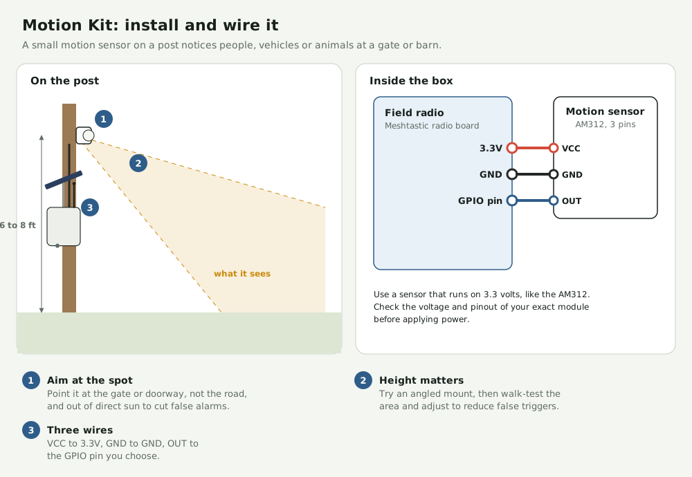
AM312 aimed down from a post with VCC, ground and output connections
Open full-size diagram ↗

Before you start · AM312 module, short jumper wires and a protected mount.

  1. Prepare the radio
    Attach its antenna before powering it. If it needs firmware, use the Meshtastic flasher with a USB data cable and select the exact model and revision.
  2. Join your ranch mesh
    Set the region to US for US915 hardware. Import the ranch channel from the base and match the modem preset. Keep the channel QR code private because it contains the channel key.
  3. Confirm the module pinout
    Check that the exact AM312 breakout supports 3.3 V. With power disconnected, connect VCC to verified 3.3 V, GND to ground and OUT to a supported GPIO.
  4. Configure Detection Sensor
    Select the GPIO. For a module that drives OUT high on motion, trigger on high and leave the pull-up off. Use an interval that limits repeated reports.
  5. Aim and walk-test
    Angle the sensor down toward the target, away from direct sun, traffic and moving vegetation. Walk across the area and verify the base receives an event. Test for false triggers before mounting.

These are example layouts. Confirm the pinout, power and fit for your exact parts. Field validation is pending.
Meshtastic flasher · Detection Sensor settings

Set it up in the app