Free shipping on all kits
← All kits

Ranch Sentinel parts list

Gate Kit

See if a gate is open and flag one that stays open.

Choose your kit

Parts kit

$239

Every part in one box. You put it together with the step-by-step guide.

Shipping included. Ships in 2 to 3 weeks.

Prefer to buy the parts yourself?

Affiliate disclosure: The current parts links are non-affiliate. We will label any paid affiliate links here.

Gate Kit

  • Low-power nRF52 Meshtastic-compatible radio, such as a US915 Heltec T114 or RAK4631 WisBlock with base boardHeltec T114 ↗ RAK4631 options ↗
  • 915 MHz antenna with a connector matched to the radioMatch to your build
  • Weatherproof enclosure, small solar panel and charge circuit matched to the selected board and cellMatch to your build
  • Compatible 18650 cell and holder with verified connector and polarityMatch to your build
  • Outdoor wired magnetic reed switch and matched magnetMatch to your build
  • Outdoor two-wire cable and a cable gland sized to the leadMatch to your build

Confirm the contact behavior and the board input supported by the setup before mounting.

How it connects

  1. 1 Reed switch + magnet
  2. 2 Compatible radio contact input
  3. 3 Ranch mesh

Connection overview. Confirm model-specific wiring and power before assembly.

Field guide · Build notes

Set up this kit

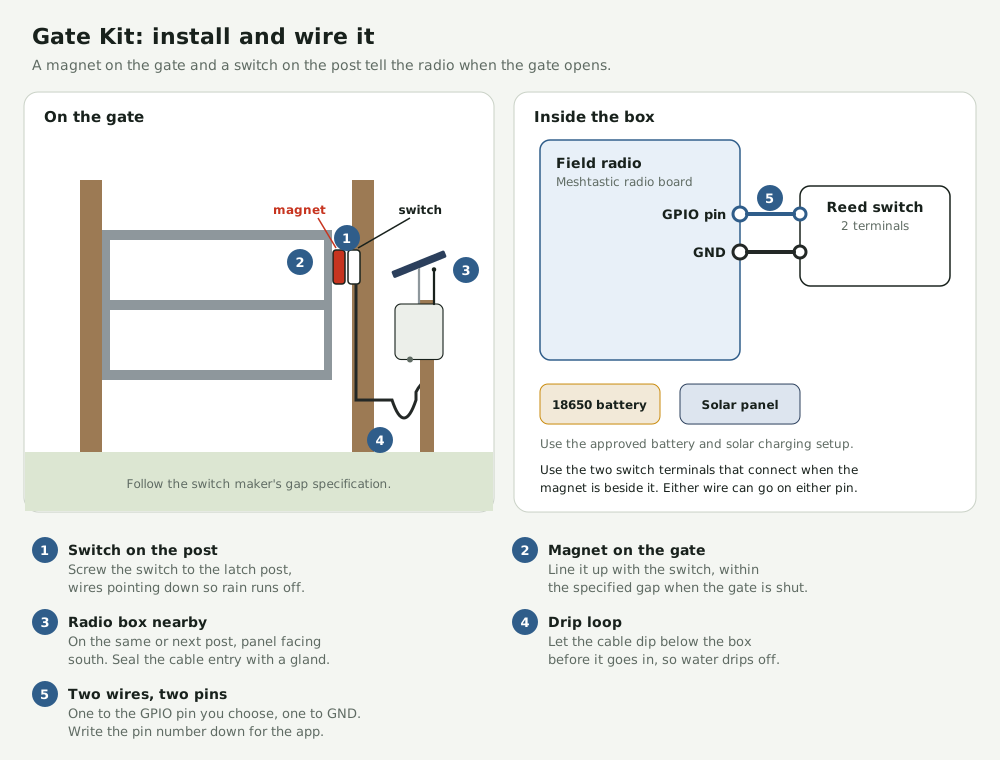
Gate magnet and post-mounted reed switch wired to field radio GPIO and ground
Open full-size diagram ↗

Before you start · Drill, screwdriver, wire stripper and a continuity tester.

  1. Prepare the radio
    Attach its antenna before powering it. If it needs firmware, use the Meshtastic flasher with a USB data cable and select the exact model and revision.
  2. Join your ranch mesh
    Set the region to US for US915 hardware. Import the ranch channel from the base and match the modem preset. Keep the channel QR code private because it contains the channel key.
  3. Wire and align the switch
    With power disconnected, wire the dry contacts to a supported GPIO and ground. Choose the contact that closes near the magnet. Mount the switch on the fixed latch post and align the magnet with the gate shut. Follow the specified gap for your switch.
  4. Configure Detection Sensor
    Choose the actual GPIO you wired. For a switch that closes to ground in the normal state, enable the pull-up if supported and trigger on high. Verify both states on the bench and choose a status interval suitable for your mesh.
  5. Weatherproof the node
    With power disconnected, verify connector polarity and the approved charging setup before attaching the battery and solar panel. Seal the cable entry with a gland and leave a drip loop.
  6. Verify both gate states
    Open and close the gate several times. Confirm fresh reports at the base from the final mount. Treat a missing report as unknown until a fresh state arrives.

These are example layouts. Confirm the pinout, power and fit for your exact parts. Field validation is pending.
Meshtastic flasher · Detection Sensor settings

Set it up in the app